ТОР 5 статей:
Методические подходы к анализу финансового состояния предприятия
Проблема периодизации русской литературы ХХ века. Краткая характеристика второй половины ХХ века
Характеристика шлифовальных кругов и ее маркировка
Служебные части речи. Предлог. Союз. Частицы
КАТЕГОРИИ:
- Археология
- Архитектура
- Астрономия
- Аудит
- Биология
- Ботаника
- Бухгалтерский учёт
- Войное дело
- Генетика
- География
- Геология
- Дизайн
- Искусство
- История
- Кино
- Кулинария
- Культура
- Литература
- Математика
- Медицина
- Металлургия
- Мифология
- Музыка
- Психология
- Религия
- Спорт
- Строительство
- Техника
- Транспорт
- Туризм
- Усадьба
- Физика
- Фотография
- Химия
- Экология
- Электричество
- Электроника
- Энергетика
Dismantling the Agitator Lantern
● Push the agitator lantern (3005) onto the shaft (3700/6000)
● Remove the lifting gear ● Connect the agitator lantern (3005) to the mounting flange (4500) — tighten the screws crosswise with half the final torque value, then with crosswise with the full torque value (final torque value → table chapter 4.4)
|


● Loosen the hexagon screws (5774) on the clamping segments (5772) and remove the clamping segments
● Push down the seal housing and evenly tighten it to the mounting flange (tightening torques → table chapter 4.4)
| ● Put the coupling part B (3010) onto the shaft ● Mount the bolting (3065/3070)) |
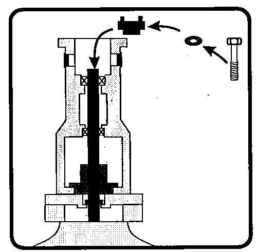
By tightening the bolt (3065) the shaft and the impeller(s) get lifted from the suspension device (5780) again — hence an increased resistance during tightening is normal
● Tighten the hexagon bolt (3065) with the tightening torque acc. to the table (→ chapter 4.4)


