ТОР 5 статей:
Методические подходы к анализу финансового состояния предприятия
Проблема периодизации русской литературы ХХ века. Краткая характеристика второй половины ХХ века
Характеристика шлифовальных кругов и ее маркировка
Служебные части речи. Предлог. Союз. Частицы
КАТЕГОРИИ:
- Археология
- Архитектура
- Астрономия
- Аудит
- Биология
- Ботаника
- Бухгалтерский учёт
- Войное дело
- Генетика
- География
- Геология
- Дизайн
- Искусство
- История
- Кино
- Кулинария
- Культура
- Литература
- Математика
- Медицина
- Металлургия
- Мифология
- Музыка
- Психология
- Религия
- Спорт
- Строительство
- Техника
- Транспорт
- Туризм
- Усадьба
- Физика
- Фотография
- Химия
- Экология
- Электричество
- Электроника
- Энергетика
Practical embedded system programming
C/C++
 Practice
 Read and remember it
 Circuitry
 Important information
ARDUINO Sketch program

Fig. 1
How does it operates:
Please, before write C++ program codes on the strings of program and then verify it. If there are not red messages on the low black screen and on the green panel of program is the message "Done Compiling", the sketch was written without error [Fig. 2].

Fig. 2
Saving sketch INO-file:
When operation had been done the compilation completely, please, press on the button of program panel File\Save [Fig. 3]. Then include folder, rename on the "File name" and "Save" it [Fig.4] or save, pressing on the red button "Close" which is placed on up side right on the panel of program.

Fig. 3

Fig.4
Compilation INO-file to HEX-file or BIN-file:
When our sketch INO-file already is saved in the certain folder, for example, Arduino, we search and open this file. When our INO-file had been opened, we press on the button "Sketch" and then here press on "Export compiled Binary" and after completely compilation it exports two HEX-files [Fig.5].

Fig.5

Here always save two HEX-files eight analog input and boot-loader:
The "eight analog input" is for programming the programmable read-only memory (PROM); rather "boot-loader" is for flashing the flesh-memory.
 By analog signals winking by the light-emitting diodes on the four pins.

/*
In this firmware can be activated address bus A0, A1, A2 and A3
This firmware operates with microcontrollers ATMEGA328P
A firmware can be debugged on the ARDUINO UNO R3
*/
void setup() {
// put your setup code here, to run once:
pinMode(14, OUTPUT); //
pinMode(15, OUTPUT); //
pinMode(16, OUTPUT); //
pinMode(17, OUTPUT); //
//
digitalWrite(14, HIGH); //set pullup on analog pin with address bus A0
digitalWrite(15, HIGH); //set pullup on analog pin with address bus A1
digitalWrite(16, HIGH); //set pullup on analog pin with address bus A2
digitalWrite(17, HIGH); //set pullup on analog pin with address bus A3
}
void loop() {
// put your main code here, to run repeatedly:
}
By analog signals, winking by the light-emitting diodes on the six pins.

/*
In this firmware can be activated address bus A0, A1, A2, A3, A4 and A5
This firmware operates with microcontrollers ATMEGA328P
A firmware can be debugged on the ARDUINO UNO R3
*/
void setup() {
// put your setup code here, to run once:
pinMode(14, OUTPUT); //
pinMode(15, OUTPUT); //
pinMode(16, OUTPUT); //
pinMode(17, OUTPUT); //
pinMode(18, OUTPUT); //
pinMode(19, OUTPUT); //
//
digitalWrite(14, HIGH); //set pullup on analog pin with address bus A0
digitalWrite(15, HIGH); //set pullup on analog pin with address bus A1
digitalWrite(16, HIGH); //set pullup on analog pin with address bus A2
digitalWrite(17, HIGH); //set pullup on analog pin with address bus A3
digitalWrite(18, HIGH); //set pullup on analog pin with address bus A4
digitalWrite(19, HIGH); //set pullup on analog pin with address bus A5
}
void loop() {
// put your main code here, to run repeatedly:
}
/*
In this firmware can be activated address bus A0, A1, A2 and A3
This firmware operates with microcontrollers ATMEGA328P
A firmware can be debugged on the ARDUINO UNO R3
*/
void setup() {
// put your setup code here, to run once:
pinMode(A0, OUTPUT); //
pinMode(A1, OUTPUT); //
pinMode(A2, OUTPUT); //
pinMode(A3, OUTPUT); //
pinMode(A4, OUTPUT); //
//
}
void loop() {
// put your main code here, to run repeatedly:
digitalWrite(A0, HIGH); //set pullup on analog pin with address bus A0
delay(50); //
digitalWrite(A0, LOW); //set pullup on analog pin with address bus A0
delay(90); //
digitalWrite(A1, HIGH); //set pullup on analog pin with address bus A1
delay(60); //
digitalWrite(A1, LOW); //set pullup on analog pin with address bus A1
delay(80); //
digitalWrite(A2, HIGH); //set pullup on analog pin with address bus A2
delay(70); //
digitalWrite(A2, LOW); //set pullup on analog pin with address bus A2
delay(70); //
digitalWrite(A3, HIGH); //set pullup on analog pin with address bus A3
delay(80); //
digitalWrite(A3, LOW); //set pullup on analog pin with address bus A3
delay(60); //
digitalWrite(A4, HIGH); //set pullup on analog pin with address bus A0
delay(90); //
digitalWrite(A4, LOW); //set pullup on analog pin with address bus A0
delay(50); //
}
 Melodic five light-emitting diodes

/*
In this firmware can be activated address bus A0, A1, A2, A3, A4 and A5.
This firmware operates with microcontrollers ATMEGA328P
A firmware can be debugged on the ARDUINO NANO or UNO R3
*/
void setup() {
Serial.begin(9600); //
Serial.available(); //
// put your setup code here, to run once:
pinMode(A0, OUTPUT); //
pinMode(A1, OUTPUT); //
pinMode(A2, OUTPUT); //
pinMode(A3, OUTPUT); //
pinMode(A4, OUTPUT); //
pinMode(A5, OUTPUT); //
//
}
void loop() {
// put your main code here, to run repeatedly:
digitalWrite(A0, HIGH); //set pullup on analog pin with address bus A0
tone(A5, 1000); //
delay(50); //
digitalWrite(A0, LOW); //set pullup on analog pin with address bus A0
tone(A5, 900); //
delay(90); //
digitalWrite(A1, HIGH); //set pullup on analog pin with address bus A1
tone(A5, 900); //
delay(60); //
digitalWrite(A1, LOW); //set pullup on analog pin with address bus A1
tone(A5, 800); //
delay(80); //
digitalWrite(A2, HIGH); //set pullup on analog pin with address bus A2
tone(A5, 700); //
delay(70); //
digitalWrite(A2, LOW); //set pullup on analog pin with address bus A2
tone(A5, 600); //
delay(70); //
digitalWrite(A3, HIGH); //set pullup on analog pin with address bus A3
tone(A5, 500); //
delay(80); //
digitalWrite(A3, LOW); //set pullup on analog pin with address bus A3
tone(A5, 400); //
delay(60); //
digitalWrite(A4, HIGH); //set pullup on analog pin with address bus A0
tone(A5, 300); //
delay(90); //
digitalWrite(A4, LOW); //set pullup on analog pin with address bus A0
tone(A5, 200); //
delay(50); //
}
Programming shift registers:

As you can see from the schematic, we are picking up +5V and a Ground connection at the Arduino board, Digital IO pins 2,3,4 are being used for the Data, Latch and the Clock. The Shift Register also requires a couple of links to pull the Reset High and the Enable Low to make these examples work. You could, of course, control these pins using the Arduino, but for these simple examples, there is no requirement to do this. A more complex project might want to take full control of the IC, but that would be up to the circuit developer.
For the coding, we will use the started Arduino IDE available for the Arduino Homepage[^].
This project's code is no different from any other Arduino project and follows the same Initialisation, Setup and Loop Structure. There are no special libraries required to be included or initialised within the code, and standard methods are all that is required to make this work. The basic structure is as follows:

int dataPin = 2; //Define which pins will be used for the Shift Register control
int latchPin = 3;
int clockPin = 4;
//Add any other variables used by the main program loop here
void setup()
{
pinMode(dataPin, OUTPUT); //Configure each IO Pin
pinMode(latchPin, OUTPUT);
pinMode(clockPin, OUTPUT);
}
void loop()
{
//Main program loop as required to go here
}
Example 1 - Single Shift Register - Binary Counter
The first example will simply create a binary counter, and show this incrementing on the LEDs.
To do this, we must first add a variable to the initialisation section which will store the counter, and then add a standard for loop to do the incrementing in the main program loop method. As this is the first example, I will show the complete program, so you can see where the variables and the loop need to be added.

int dataPin = 2; //Define which pins will be used for the Shift Register control
int latchPin = 3;
int clockPin = 4;
int counter = 0; //The counter for storing the byte value
void setup()
{
pinMode(dataPin, OUTPUT); //Configure each IO Pin
pinMode(latchPin, OUTPUT);
pinMode(clockPin, OUTPUT);
}
void loop()
{
for (counter = 0; counter < 256; counter++)
{
digitalWrite(latchPin, LOW); //Pull latch LOW to start sending data
shiftOut(dataPin, clockPin, MSBFIRST, counter); //Send the data
digitalWrite(latchPin, HIGH); //Pull latch HIGH to stop sending data
delay(500);
}
}
As you can see in the main program loop, a simple for loop increments the counter byte. When we are ready to send the new byte value to the shift register, we must first pull the latchPin LOW. We then send out the data to the shift register (in the correct bit orientation). Once the data has been sent, we pull the latchPin HIGH again to signal that we are finished. The delay instruction simply allows us to control how quickly we write out the bytes to the register, in this case, we are waiting 500milliseconds between increments.
Example 2 - Single Shift Register - LED Sweep
No article involving LEDs and shift registers would be complete unless it includes the trusty Knight Rider KITT Light sweep!
To do this, first we need to set up a byte array to store each of the values in the sweep. If you think about what is happening, all we are doing is turning each bit on and off in sequence, so it would be 10000000, 01000000, 00100000, 00010000, etc. etc. These values are then in turn written out to the shift register.

int dataPin = 2; //Define which pins will be used for the Shift Register control
int latchPin = 3;
int clockPin = 4;
int seq[14] = {1,2,4,8,16,32,64,128,64,32,16,8,4,2}; //The byte sequence
void setup()
{
pinMode(dataPin, OUTPUT); //Configure each IO Pin
pinMode(latchPin, OUTPUT);
pinMode(clockPin, OUTPUT);
}
void loop()
{
for (int n = 0; n < 14; n++)
{
digitalWrite(latchPin, LOW); //Pull latch LOW to start sending data
shiftOut(dataPin, clockPin, MSBFIRST, seq[n]); //Send the data
digitalWrite(latchPin, HIGH); //Pull latch HIGH to stop sending data
delay(75);
}
}
Moving On - Dual Shift Registers
One of the nice features about the Shift Registers is they have a pin called Overflow, and what this basically allows us to do is write more data to the first shift register than it can handle, and it will overflow this excess to this pin. So to extend the chain, we simply connect the first shift registers Overflow to the second shift registers Data pin. This way, if we write out 2 bytes to the first shift register, the first byte is passed onto the second shift register, and the second byte is retained within the first shift register. The schematic below shows how this cascade is connected up, I have also added 3 additional LEDs so we can monitor the DATA, CLOCK and OVERFLOW pins.

For the dual shift register setup, the code is almost identical, the only difference is that we add a second byte array variable and an additional line to write the second byte. To demonstrate this, we will extend the binary counter example from 8 to 16 Bit.
Example 3 - Dual Shift Register - 16Bit Binary Increment
int dataPin = 2; //Define which pins will be used for the Shift Register control
int latchPin = 3;
int clockPin = 4;
int byte1 = 0; //The counter for storing the byte #1 value
int byte2 = 0; //The counter for storing the byte #2 value
void setup()
{
pinMode(dataPin, OUTPUT); //Configure each IO Pin
pinMode(latchPin, OUTPUT);
pinMode(clockPin, OUTPUT);
}
void loop()
{
for (byte2 = 0; byte2 < 256; byte2++) //Outer Loop
{
for (byte1 = 0; byte1 < 256; byte1++) //Inner Loop
{
digitalWrite(latchPin, LOW); //Pull latch LOW to start sending data
shiftOut(dataPin, clockPin, MSBFIRST, byte1); //Send the data byte 1
shiftOut(dataPin, clockPin, MSBFIRST, byte2); //Send the data byte 2
digitalWrite(latchPin, HIGH); //Pull latch HIGH to stop sending data
delay(250);
}
}
}
Example 4 - Dual Shift Register - KITT is back!
Just like the TV program, KITT made a re-appearance, but the new version had a dual sweep light on the front of the car. To achieve this, we need two arrays to store the left and right (Byte 1 + 2) values, and again an additional line to write out the second byte.
int dataPin = 2; //Define which pins will be used for the Shift Register control
int latchPin = 3;
int clockPin = 4;
int seq1[14] = {1,2,4,8,16,32,64,128,64,32,16,8,4,2}; //The array for storing the
// byte #1 value
int seq2[14] = {128,64,32,16,8,4,2,1,2,4,8,16,32,64}; //The array for storing the
// byte #2 value
void setup()
{
pinMode(dataPin, OUTPUT); //Configure each IO Pin
pinMode(latchPin, OUTPUT);
pinMode(clockPin, OUTPUT);
}
void loop()
{
for (int x = 0; x < 14; x++) //Array Index
{
digitalWrite(latchPin, LOW); //Pull latch LOW to start sending data
shiftOut(dataPin, clockPin, MSBFIRST, seq1[x]); //Send the data byte 1
shiftOut(dataPin, clockPin, MSBFIRST, seq2[x]); //Send the data byte 2
digitalWrite(latchPin, HIGH); //Pull latch HIGH to stop sending data
delay(75);
}
}
 By digital signals, winking by the light-emitting diodes on the six pins. Including six green light-emitting diodes and four red light-emitting diodes.

/*
In this firmware can be activated address bus A0, A1, A2, A3, SDA and SCL
All address bus A0-A3 have receive the signals
All two wire interface i2c SDA and SCL have send the signals
This firmware operates with microcontrollers ATMEGA328P
A firmware can be debugged on the ARDUINO UNO R3
*/
//It includes a protocol into input/output of AVR
#include<avr/io.h>
//It includes a protocol into wired devices
#include<Wire.h>
void setup() {
// put your setup code here, to run once:
//It initializes functions of the pin modes through the protocol of wire
pinMode(A0, OUTPUT); //
pinMode(A1, OUTPUT); //
pinMode(A2, OUTPUT); //
pinMode(A3, OUTPUT); //
pinMode(SDA, OUTPUT); //
pinMode(SCL, OUTPUT); //
//It initializes functions of the digital writes from main device to peripheral devices
digitalWrite(A0, HIGH); //
delay(50);
digitalWrite(A0, LOW); //
delay(50);
digitalWrite(A1, HIGH); //
delay(50);
digitalWrite(A1, LOW); //
delay(50);
digitalWrite(A2, HIGH); //
delay(50);
digitalWrite(A2, LOW); //
delay(50);
digitalWrite(A3, HIGH); //
delay(50);
digitalWrite(A3, LOW); //
delay(50);
digitalWrite(SDA, HIGH); //
digitalWrite(SCL, HIGH); //
}
void loop() {
// After creating a setup() function, which initializes and sets the initial values, the loop() function does precisely what its name suggests, and loops consecutively, allowing your program to change and respond. Use it to actively control the Arduino board.
}
 //It is tested on Arduino IDE 1.0.5
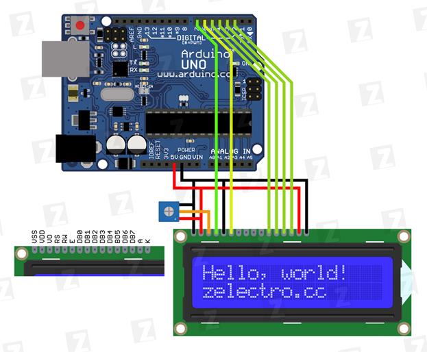
#include <LiquidCrystal.h> // adding library of liquid crystal display
LiquidCrystal lcd(7, 6, 5, 4, 3, 2); // (RS, E, DB4, DB5, DB6, DB7)
void setup(){
lcd.begin(16, 2); // Задаем размерность экрана
lcd.setCursor(0, 0); // Устанавливаем курсор в начало 1 строки
lcd.print("Hello, world!"); // Выводим текст
lcd.setCursor(0, 1); // Устанавливаем курсор в начало 2 строки
lcd.print("zelectro.cc"); // Выводим текст
}
void loop(){
}

// It is tested on Arduino IDE 1.0.5
#include <Wire.h>
#include <LiquidCrystal.h> // adding library of liquid crystal display
// Битовая маска символа улыбки
byte smile[8] =
{
B00010,
B00001,
B11001,
B00001,
B11001,
B00001,
B00010,
};
LiquidCrystal lcd(7, 6, 5, 4, 3, 2); // (RS, E, DB4, DB5, DB6, DB7)
void setup(){
lcd.begin(16, 2); // Задаем размерность экрана
lcd.createChar(1, smile); // Создаем символ под номером 1
lcd.setCursor(0, 0); // Устанавливаем курсор в начало 1 строки
lcd.print("\1"); // Выводим смайлик (символ под номером 1) - "\1"
}
void loop(){
}
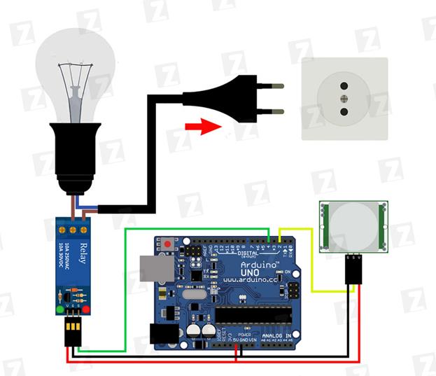
//Тестировалось на Arduino IDE 1.0.1
//Время калибровки датчика (10-60 сек. по даташиту)
int calibrationTime = 30;
//Время, в которое был принят сигнал отсутствия движения(LOW)
long unsigned int lowIn;
//Пауза, после которой движение считается оконченным
long unsigned int pause = 5000;
//Флаг. false = значит движение уже обнаружено, true - уже известно, что движения нет
boolean lockLow = true;
//Флаг. Сигнализирует о необходимости запомнить время начала отсутствия движения
boolean takeLowTime;
int pirPin = 2; //вывод подключения PIR датчика
int ledPin = 13; //вывод сигнального диода
int relayPin = 4; //реле пин
void setup()
{
pinMode(pirPin, INPUT); //
pinMode(ledPin, OUTPUT); //
pinMode(relayPin, OUTPUT); //
//!ВНИМАНИЕ! При использовании n-p-n реле необходимо в след. строчке поменять HIGH на LOW
digitalWrite(relayPin, HIGH);
delay(4000);
digitalWrite(pirPin, LOW);
//дадим датчику время на калибровку
for(int i = 0; i < calibrationTime; i++)
{
//Во время калибровки будет мигать сигнальный диод
i % 2? digitalWrite(ledPin, HIGH): digitalWrite(ledPin, LOW);
delay(1000);
}
//По окончанию калибровки зажжем сигнальный диод
digitalWrite(ledPin, HIGH);
delay(50);
}
void loop()
{
//Если обнаружено движение
if(digitalRead(pirPin) == HIGH)
{
//Если до этого момента еще не включили реле
if(lockLow)
{
lockLow = false;
//Включаем реле.
//!ВНИМАНИЕ! При использовании n-p-n реле необходимо в след. строчке поменять LOW на HIGH
digitalWrite(relayPin, LOW);
delay(50);
}
takeLowTime = true;
}
//Ели движения нет
if(digitalRead(pirPin) == LOW)
{
//Если время окончания движения еще не записано
if(takeLowTime)
{
lowIn = millis(); //Сохраним время окончания движения
takeLowTime = false; //Изменим значения флага, чтобы больше не брать время, пока не будет нового движения
}
//Если время без движение превышает паузу => движение окончено
if(!lockLow && millis() - lowIn > pause)
{
//Изменяем значение флага, чтобы эта часть кода исполнилась лишь раз, до нового движения
lockLow = true;
digitalWrite(relayPin, HIGH);
delay(50);
}
}
}


//Тестировалось на Arduino IDE 1.0.1
#include <SD.h>
File originalFile; // Файл который будет скопирован
File copiedFile; // Файл - копия
char* ORIGINAL_FILE_NAME = "1.txt"; // Название копируемого файла
char* COPIED_FILE_NAME = "2.txt"; // Название файла копии
char fileText[255]; // Хранилище для текста содержащегося в копируемом файле
void setup()
{
Serial.begin(9600);
// SPI SS пин должен быть OUTPUT
pinMode(10, OUTPUT);
// Инициализируем СД карту
Serial.print("Initializing SD card...");
if (!SD.begin(4)) {
Serial.println("initialization failed!");
return;
}
Serial.println("initialization done.");
// Открываем первый файл
originalFile = SD.open(ORIGINAL_FILE_NAME);
if (originalFile) {
Serial.println(ORIGINAL_FILE_NAME);
// Считываем текст из 1 файла
int i = 0;
while (originalFile.available()) {
char c = originalFile.read();
fileText[i++] = c;
Serial.write(c);
}
fileText[i] = 0;
// Закрываем файл
originalFile.close();
} else {
// Если произошла ошибка открытия файла, выводим сообщение
Serial.print("error opening ");
Serial.println(ORIGINAL_FILE_NAME);
}
// Открываем (или создаем, если его нет) файл копии
copiedFile = SD.open(COPIED_FILE_NAME, FILE_WRITE);
// Записываем в него считанный текст
if (copiedFile) {
Serial.print("Copying...");
copiedFile.println(fileText);
// Закрываем файл
copiedFile.close();
Serial.println("done.");
} else {
// Если произошла ошибка открытия файла, выводим сообщение
Serial.print("error opening ");
Serial.println(COPIED_FILE_NAME);
}
}
// Весь код был выполнен в функции setup
void loop()
{
}
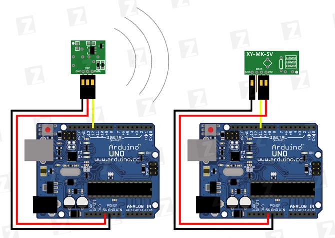
// Тестировалось на Arduino IDE 1.0.1
#include <VirtualWire.h>
void setup()
{
Serial.begin(9600);
vw_set_ptt_inverted(true); // Необходимо для DR3100
vw_setup(2000); // Задаем скорость приема
vw_rx_start(); // Начинаем мониторинг эфира
}
void loop()
{
uint8_t buf[VW_MAX_MESSAGE_LEN]; // Буфер для сообщения
uint8_t buflen = VW_MAX_MESSAGE_LEN; // Длина буфера
if (vw_get_message(buf, &buflen)) // Если принято сообщение
{
// Начинаем разбор
int i;
// Если сообщение адресовано не нам, выходим
if (buf[0]!= 'z')
{
return;
}
char command = buf[2]; // Команда находится на индексе 2
// Числовой параметр начинается с индекса 4
i = 4;
int number = 0;
// Поскольку передача идет посимвольно, то нужно преобразовать набор символов в число
while (buf[i]!= ' ')
{
number *= 10;
number += buf[i] - '0';
i++;
}
Serial.print(command);
Serial.print(" ");
Serial.println(number);
}
}


int val;
int LED = 13;
void setup()
{
Serial.begin(9600);
pinMode(LED, OUTPUT);
}
void loop()
{
if (Serial.available())
{
val = Serial.read();
// При символе "W" включаем светодиод
if (val == 'W')
{
digitalWrite(LED, HIGH);
}
// При символе "S" выключаем светодиод
if (val == 'S')
{
digitalWrite(LED, LOW);
}
}
}


// Реле модуль подключен к цифровому выводу 4
int Relay = 4;
void setup()
{
pinMode(Relay, OUTPUT);
}
void loop()
{
digitalWrite(Relay, LOW); // реле включено
delay(2000);
digitalWrite(Relay, HIGH); // реле выключено
delay(2000);
}
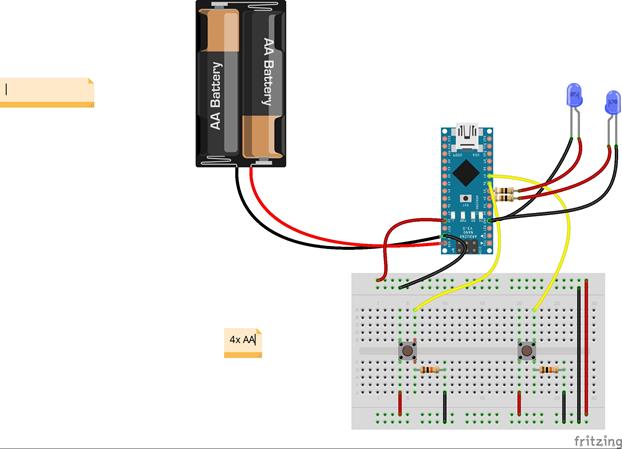
Button:
Pushbuttons or switches connect two points in a circuit when you press them. This example turns on the built-in LED on pin 13 when you press the button.
Hardware
- Arduino or Genuino Board
- Momentary button or Switch
- 10K ohm resistor
- hook-up wires
- breadboard
- Circuit

/*
Button
Turns on and off a light emitting diode(LED) connected to digital
pin 13, when pressing a pushbutton attached to pin 2.
The circuit:
* LED attached from pin 13 to ground
* pushbutton attached to pin 2 from +5V
* 10K resistor attached to pin 2 from ground
* Note: on most Arduinos there is already an LED on the board
attached to pin 13.
created 2005
by DojoDave <http://www.0j0.org>
modified 30 Aug 2011
by Tom Igoe
This example code is in the public domain.
http://www.arduino.cc/en/Tutorial/Button
*/
// constants won't change. They're used here to
// set pin numbers:
const int buttonPin = 2; // the number of the pushbutton pin
const int ledPin = 13; // the number of the LED pin
// variables will change:
int buttonState = 0; // variable for reading the pushbutton status
void setup() {
// initialize the LED pin as an output:
pinMode(ledPin, OUTPUT);
// initialize the pushbutton pin as an input:
pinMode(buttonPin, INPUT);
}
void loop() {
// read the state of the pushbutton value:
buttonState = digitalRead(buttonPin);
// check if the pushbutton is pressed.
// if it is, the buttonState is HIGH:
if (buttonState == HIGH) {
// turn LED on:
digitalWrite(ledPin, HIGH);
} else {
// turn LED off:
digitalWrite(ledPin, LOW);
}
}

#include <avr/io.h>
int main()
{
//high nibble for output(columns) low for input(rows);
DDRB=0xF0;
//enable internal pullups for PB0-PB3
PORTB=0x0F;
//Port D for indication only
DDRD=0xFF;
while (1) //loop key check forever
{
//first column
PORTB =0b01111111;
//check for rows and send key number to portD
//instead sending key number to PORTD you can use
// any function that serves pressed button
if (bit_is_set(PINB, 3)) PORTD=1;
if (bit_is_set(PINB, 2)) PORTD=2;
if (bit_is_set(PINB, 1)) PORTD=3;
if (bit_is_set(PINB, 0)) PORTD=4;
//second column
PORTB =0b10111111;
if (bit_is_set(PINB, 3)) PORTD=5;
if (bit_is_set(PINB, 2)) PORTD=6;
if (bit_is_set(PINB, 1)) PORTD=7;
if (bit_is_set(PINB, 0)) PORTD=8;
//third column
PORTB =0b11011111;
if (bit_is_set(PINB, 3)) PORTD=9;
if (bit_is_set(PINB, 2)) PORTD=10;
if (bit_is_set(PINB, 1)) PORTD=11;
if (bit_is_set(PINB, 0)) PORTD=12;
//fourth column
PORTB =0b11101111;
if (bit_is_set(PINB, 3)) PORTD=13;
if (bit_is_set(PINB, 2)) PORTD=14;
if (bit_is_set(PINB, 1)) PORTD=15;
if (bit_is_set(PINB, 0)) PORTD=16;
}
}

/*
LiquidCrystal Library - Autoscroll
Demonstrates the use a 16x2 LCD display. The LiquidCrystal
library works with all LCD displays that are compatible with the
Hitachi HD44780 driver. There are many of them out there, and you
can usually tell them by the 16-pin interface.
This sketch demonstrates the use of the autoscroll()
and noAutoscroll() functions to make new text scroll or not.
The circuit:
* LCD RS pin to digital pin 12
* LCD Enable pin to digital pin 11
* LCD D4 pin to digital pin 5
* LCD D5 pin to digital pin 4
* LCD D6 pin to digital pin 3
* LCD D7 pin to digital pin 2
* LCD R/W pin to ground
* 10K resistor:
* ends to +5V and ground
* wiper to LCD VO pin (pin 3)
Library originally added 18 Apr 2008
by David A. Mellis
library modified 5 Jul 2009
by Limor Fried (http://www.ladyada.net)
example added 9 Jul 2009
by Tom Igoe
modified 22 Nov 2010
by Tom Igoe
This example code is in the public domain.
http://www.arduino.cc/en/Tutorial/LiquidCrystalAutoscroll
*/
// include the library code:
#include <LiquidCrystal.h>
// initialize the library with the numbers of the interface pins
LiquidCrystal lcd(12, 11, 5, 4, 3, 2);
void setup() {
// set up the LCD's number of columns and rows:
lcd.begin(16, 2);
}
void loop() {
// set the cursor to (0,0):
lcd.setCursor(0, 0);
// print from 0 to 9:
for (int thisChar = 0; thisChar < 10; thisChar++) {
lcd.print(thisChar);
delay(500);
}
// set the cursor to (16,1):
lcd.setCursor(16, 1);
// set the display to automatically scroll:
lcd.autoscroll();
// print from 0 to 9:
for (int thisChar = 0; thisChar < 10; thisChar++) {
lcd.print(thisChar);
delay(500);
}
// turn off automatic scrolling
lcd.noAutoscroll();
// clear screen for the next loop:
lcd.clear();
}
Write firmware for liquid-crystal display, using variables with pin modes as INT0; INT1; D4; D5; D6; D7; RS; E and so on.

//It is tested on Arduino IDE 1.0.5
int MCU_PD2_INT0 = 2;
int MCU_PD3_INT1 = 3;
int MCU_PD4_D4 = 4;
int MCU_PD5_D5 = 5;
int MCU_PD6_D6 = 6;
int MCU_PD7_D7 = 7;
const int LED_RS = 2;
const int LED_E = 3;
const int LED_DB4 = 4;
const int LED_DB5 = 5;
const int LED_DB6 = 6;
const int LED_DB7 = 7;
#include <LiquidCrystal.h> // adding library of liquid crystal display
LiquidCrystal lcd(LED_RS, LED_E, LED_DB4, LED_DB5, LED_DB6, LED_DB7); // (RS, E, DB4, DB5, DB6, DB7)
void setup(){
Serial.begin(9600); //
lcd.begin(0, 0); // beginning of the sizes of liquid crystal display
lcd.setCursor(0, 0); // It sets the cursor of liquid-crystal display
lcd.print("God loves you"); // It displays characters and digits
}
void loop(){
}
Winking of the digits by the liquid crystal display:

/*
This firmware operates with microcontroller ATMEGA328P
This firmware can be debugged on the Arduino UNO R3
This firmware can be flashed by any professional programmer which supports a microcontroller ATMEGA328P
It operates with liquid crystal display LCD-1602
Designed by Dmitry
*/
//it configures device drivers:
#include<LiquidCrystal.h>
LiquidCrystal lcd(2, 3, 4, 5, 6, 7); //(RS, EN, D4, D5, D6, D7)
//it displays digits and characters:
unsigned char Input_number; //
void setup() {
// put your setup code here, to run once:
Serial.begin(9600); //
lcd.setCursor(2, 4); //
lcd.begin(16, 2); //
lcd.print("1"); //
delay(1000); //
lcd.print("2"); //
delay(1000); //
lcd.print("3"); //
delay(1000); //
lcd.print("4"); //
delay(1000); //
lcd.print("5"); //
delay(1000); //
lcd.print("6"); //
delay(1000); //
lcd.print("7"); //
delay(1000); //
lcd.print("8"); //
delay(1000); //
lcd.print("9"); //
delay(1000); //
lcd.print("0"); //
delay(1000); //
lcd.print("#"); //
delay(1000); //
lcd.print("*"); //
delay(1000); //
lcd.println(Input_number); //
}
void loop() {
// put your main code here, to run repeatedly:
}
Winking of the relays

// Прошивка блока "А" исполнительных реле
String input_string = "";
void setup() {
Serial.begin(9600);
pinMode(4, OUTPUT); //
pinMode(5, OUTPUT); //
pinMode(6, OUTPUT); //
pinMode(7, OUTPUT); //
pinMode(8, OUTPUT); //
pinMode(9, OUTPUT); //
pinMode(10, OUTPUT); //
pinMode(11, OUTPUT); //
digitalWrite(4,HIGH); //
digitalWrite(5,HIGH); //
digitalWrite(6,HIGH); //
digitalWrite(7,HIGH); //
digitalWrite(8,HIGH); //
digitalWrite(9,HIGH); //
digitalWrite(10,HIGH); //
digitalWrite(11,HIGH); //
}
void loop() {
while (Serial.available() > 0) {
char c = Serial.read();
if (c == '\n') {
// Дебаг
Serial.print("Input_string is: ");
Serial.println(input_string);
if (input_string=="a4off"){digitalWrite(4,HIGH);}
if (input_string=="a4on"){digitalWrite(4,LOW);}
if (input_string=="a5off"){digitalWrite(5,HIGH);}
if (input_string=="a5on"){digitalWrite(5,LOW);}
if (input_string=="a6off"){digitalWrite(6,HIGH);}
if (input_string=="a6on"){digitalWrite(6,LOW);}
if (input_string=="a7off"){digitalWrite(7,HIGH);}
if (input_string=="a7on"){digitalWrite(7,LOW);}
if (input_string=="a8off"){digitalWrite(8,HIGH);}
if (input_string=="a8on"){digitalWrite(8,LOW);}
if (input_string=="a9off"){digitalWrite(9,HIGH);}
if (input_string=="a9on"){digitalWrite(9,LOW);}
if (input_string=="a10off"){digitalWrite(10,HIGH);}
if (input_string=="a10on"){digitalWrite(10,LOW);}
if (input_string=="a11off"){digitalWrite(11,HIGH);}
if (input_string=="a11on"){digitalWrite(11,LOW);}
if (input_string=="test"){for (int i=4; i <= 11; i++){ digitalWrite(i,LOW); delay(1000);}
for (int i=4; i <= 11; i++){ digitalWrite(i,HIGH); delay(1000);}}
input_string = "";
} else {input_string += c;}
}
}
/*
Adafruit Arduino - Lesson 12. Light and Temperature
*/
#include <LiquidCrystal.h>
int tempPin = 0;
int lightPin = 1;
// BS E D4 D5 D6 D7
LiquidCrystal lcd(7, 8, 9, 10, 11, 12);
void setup()
{
lcd.begin(16, 2);
}
void loop()
{
// Display Temperature in C
int tempReading = analogRead(tempPin);
float tempVolts = tempReading * 5.0 / 1024.0;
float tempC = (tempVolts - 0.5) * 100.0;
float tempF = tempC * 9.0 / 5.0 + 32.0;
// ----------------
lcd.print("Temp F ");
lcd.setCursor(6, 0);
lcd.print(tempF);
// Display Light on second row
int lightReading = analogRead(lightPin);
lcd.setCursor(0, 1);
// ----------------
lcd.print("Light ");
lcd.setCursor(6, 1);
lcd.print(lightReading);
delay(500);
}


/*
http://www.circuitstoday.com/interfacing-hex-keypad-to-arduino
*/
int row[]={6,7,8,9};// Defining row pins of keypad connected to Aeduino pins
int col[]={10,11,12,13};//Defining column pins of keypad connected to Arduino
int i,j; // Two counter variables to count inside for loop
int col_scan; // Variable to hold value of scanned columns
void setup()
{
Serial.begin(9600);
for(i=0;i<=3;i++)
{
pinMode(row[i],OUTPUT);
pinMode(col[i],INPUT);
digitalWrite(col[i],HIGH);
} }
void loop()
{
for(i=0; i<=3; i++)
{
digitalWrite(row[0],HIGH);
digitalWrite(row[1],HIGH);
digitalWrite(row[2],HIGH);
digitalWrite(row[3],HIGH);
digitalWrite(row[i],LOW);
for(j=0; j<=3; j++)
{
col_scan=digitalRead(col[j]);
if(col_scan==LOW)
{
keypress(i,j);
delay(300);
}}
}}
void keypress(int i, int j)
{
if(i==0&&j==0)
Serial.println("1");
if(i==0&&j==1)
Serial.println("2");
if(i==0&&j==2)
Serial.println("3");
if(i==0&&j==3)
Serial.println("A");
if(i==1&&j==0)
Serial.println("4");
if(i==1&&j==1)
Serial.println("5");
if(i==1&&j==2)
Serial.println("6");
if(i==1&&j==3)
Serial.println("B");
if(i==2&&j==0)
Serial.println("7");
if(i==2&&j==1)
Serial.println("8");
if(i==2&&j==2)
Serial.println("9");
if(i==2&&j==3)
Serial.println("C");
if(i==3&&j==0)
Serial.println("*");
if(i==3&&j==1)
Serial.println("0");
if(i==3&&j==2)
Serial.println("#");
if(i==3&&j==3)
Serial.println("D");
}

// задаем константы
const int buttonPin = 2; // номер входа, подключенный к кнопке
const int ledPin = 13; // номер выхода светодиода
// переменные
int buttonState = 3; // переменная для хранения состояния кнопки
int buttonCnt = 0; // переменная для защиты от дребезга кнопки
void setup() {
// инициализируем пин, подключенный к светодиоду, как выход
pinMode(ledPin, OUTPUT);
// инициализируем пин, подключенный к кнопке, как вход
pinMode(buttonPin, INPUT);
// настраиваем последовательный порт
Serial.begin(9600);
}
void loop(){
// обработка дребезга кнопки
delay(1);
if (buttonState!= digitalRead(buttonPin)) buttonCnt++; else buttonCnt = 0;
if (buttonCnt > 100)
{
// считываем значения с входа кнопки
buttonState = digitalRead(buttonPin);
buttonCnt = 0;
// проверяем нажата ли кнопка
// если нажата, то buttonState будет LOW:
if (buttonState == LOW) {
// включаем светодиод
digitalWrite(ledPin, HIGH);
// отправляем команду
Serial.print("ON_1");
} else {
// выключаем светодиод
digitalWrite(ledPin, LOW);
// отправляем команду
Serial.print("OFF_1");
}
}
}

/* Play Melody
* -----------
*
* Program to play a simple melody
*
* Tones are created by quickly pulsing a speaker on and off
* using PWM, to create signature frequencies.
*
* Each note has a frequency, created by varying the period of
* vibration, measured in microseconds. We'll use pulse-width
* modulation (PWM) to create that vibration.
* We calculate the pulse-width to be half the period; we pulse
* the speaker HIGH for 'pulse-width' microseconds, then LOW
* for 'pulse-width' microseconds.
* This pulsing creates a vibration of the desired frequency.
*
* (cleft) 2005 D. Cuartielles for K3
* Refactoring and comments 2006 clay.shirky@nyu.edu
* See NOTES in comments at end for possible improvements
*/
// TONES ==========================================
// Start by defining the relationship between
// note, period, & frequency.
#define c 3830 // 261 Hz
#define d 3400 // 294 Hz
#define e 3038 // 329 Hz
#define f 2864 // 349 Hz
#define g 2550 // 392 Hz
#define a 2272 // 440 Hz
#define b 2028 // 493 Hz
#define C 1912 // 523 Hz
// Define a special note, 'R', to represent a rest
#define R 0
// SETUP ============================================
// Set up speaker on a PWM pin (digital 9, 10 or 11)
int speakerOut = 9;
// Do we want debugging on serial out? 1 for yes, 0 for no
int DEBUG = 1;
void setup() {
pinMode(speakerOut, OUTPUT);
if (DEBUG) {
Serial.begin(9600); // Set serial out if we want debugging
}
}
// MELODY and TIMING =======================================
// melody[] is an array of notes, accompanied by beats[],
// which sets each note's relative length (higher #, longer note)
int melody[] = { C, b, g, C, b, e, R, C, c, g, a, C };
int beats[] = { 16, 16, 16, 8, 8, 16, 32, 16, 16, 16, 8, 8 };
int MAX_COUNT = sizeof(melody) / 2; // Melody length, for looping.
// Set overall tempo
long tempo = 10000;
// Set length of pause between notes
int pause = 1000;
// Loop variable to increase Rest length
int rest_count = 100; //<-BLETCHEROUS HACK; See NOTES
// Initialize core variables
int tone_ = 0;
int beat = 0;
long duration = 0;
// PLAY TONE ==============================================
// Pulse the speaker to play a tone for a particular duration
void playTone() {
long elapsed_time = 0;
if (tone_ > 0) { // if this isn't a Rest beat, while the tone has
// played less long than 'duration', pulse speaker HIGH and LOW
while (elapsed_time < duration) {
digitalWrite(speakerOut,HIGH);
delayMicroseconds(tone_ / 2);
// DOWN
digitalWrite(speakerOut, LOW);
delayMicroseconds(tone_ / 2);
// Keep track of how long we pulsed
elapsed_time += (tone_);
}
}
else { // Rest beat; loop times delay
for (int j = 0; j < rest_count; j++) { // See NOTE on rest_count
delayMicroseconds(duration);
}
}
}
// LET THE WILD RUMPUS BEGIN =============================
void loop() {
// Set up a counter to pull from melody[] and beats[]
for (int i=0; i<MAX_COUNT; i++) {
tone_ = melody[i];
beat = beats[i];
duration = beat * tempo; // Set up timing
playTone();
// A pause between notes...
delayMicroseconds(pause);
if (DEBUG) { // If debugging, report loop, tone, beat, and duration
Serial.print(i);
Serial.print(":");
Serial.print(beat);
Serial.print(" ");
Serial.print(tone_);
Serial.print(" ");
Serial.println(duration);
}
}
}
/*
* NOTES
* The program purports to hold a tone for 'duration' microseconds.
* Lies lies lies! It holds for at least 'duration' microseconds, _plus_
* any overhead created by incremeting elapsed_time (could be in excess of
* 3K microseconds) _plus_ overhead of looping and two digitalWrites()
*
* As a result, a tone of 'duration' plays much more slowly than a rest
* of 'duration.' rest_count creates a loop variable to bring 'rest' beats
* in line with 'tone' beats of the same length.
*
* rest_count will be affected by chip architecture and speed, as well as
* overhead from any program mods. Past behavior is no guarantee of future
* performance. Your mileage may vary. Light fuse and get away.
*
* This could use a number of enhancements:
* ADD code to let the programmer specify how many times the melody should
* loop before stopping
* ADD another octave
* MOVE tempo, pause, and rest_count to #define statements
* RE-WRITE to include volume, using analogWrite, as with the second program at
* http://www.arduino.cc/en/Tutorial/PlayMelody
* ADD code to make the tempo settable by pot or other input device
* ADD code to take tempo or volume settable by serial communication
* (Requires 0005 or higher.)
* ADD code to create a tone offset (higer or lower) through pot etc
* REPLACE random melody with opening bars to 'Smoke on the Water'
*/
/* Play Melody
* -----------
*
* Program to play melodies stored in an array, it requires to know
* about timing issues and about how to play tones.
*
* The calculation of the tones is made following the mathematical
* operation:
*
* timeHigh = 1/(2 * toneFrequency) = period / 2
*
* where the different tones are described as in the table:
*
* note frequency period PW (timeHigh)
* c 261 Hz 3830 1915
* d 294 Hz 3400 1700
* e 329 Hz 3038 1519
* f 349 Hz 2864 1432
* g 392 Hz 2550 1275
* a 440 Hz 2272 1136
* b 493 Hz 2028 1014
* C 523 Hz 1912 956
*
* (cleft) 2005 D. Cuartielles for K3
*/
int ledPin = 13;
int speakerOut = 9;
byte names[] = {'c', 'd', 'e', 'f', 'g', 'a', 'b', 'C'};
int tones[] = {1915, 1700, 1519, 1432, 1275, 1136, 1014, 956};
byte melody[] = "2d2a1f2c2d2a2d2c2f2d2a2c2d2a1f2c2d2a2a2g2p8p8p8p";
// count length: 1 2 3 4 5 6 7 8 9 0 1 2 3 4 5 6 7 8 9 0 1 2 3 4 5 6 7 8 9 0
// 10 20 30
int count = 0;
int count2 = 0;
int count3 = 0;
int MAX_COUNT = 24;
int statePin = LOW;
void setup() {
pinMode(ledPin, OUTPUT);
}
void loop() {
analogWrite(speakerOut, 0);
for (count = 0; count < MAX_COUNT; count++) {
statePin =!statePin;
digitalWrite(ledPin, statePin);
for (count3 = 0; count3 <= (melody[count*2] - 48) * 30; count3++) {
for (count2=0;count2<8;count2++) {
if (names[count2] == melody[count*2 + 1]) {
analogWrite(speakerOut,500);
delayMicroseconds(tones[count2]);
analogWrite(speakerOut, 0);
delayMicroseconds(tones[count2]);
}
if (melody[count*2 + 1] == 'p') {
// make a pause of a certain size
analogWrite(speakerOut, 0);
delayMicroseconds(500);
}
}
}
}
}
#include <SPI.h>
#include <TFT.h> // Arduino TFT library
#define TFT_CS 10
#define TFT_DC 9
#define TFT_RST 8
TFT screen = TFT(TFT_CS, TFT_DC, TFT_RST);
void setup() {
// initialize the screen
screen.begin();
// make the background black
screen.background(0,0,0);
// set the stroke color to white
screen.fill(255,255,255);
// default text size
screen.setTextSize(1);
// write text to the screen in the top left corner
screen.text("Testing!", 0, 0);
// increase text size
screen.setTextSize(5);
// write text to the screen below
screen.text("BIG!", 0, 10);
}
void loop() {
}
/* switch
*
* Each time the input pin goes from LOW to HIGH (e.g. because of a push-button
* press), the output pin is toggled from LOW to HIGH or HIGH to LOW. There's
* a minimum delay between toggles to debounce the circuit (i.e. to ignore
* noise).
*
* David A. Mellis
* 21 November 2006
*/
int inPin = 2; // the number of the input pin
int outPin = 13; // the number of the output pin
int state = HIGH; // the current state of the output pin
int reading; // the current reading from the input pin
int previous = LOW; // the previous reading from the input pin
// the follow variables are long's because the time, measured in miliseconds,
// will quickly become a bigger number than can be stored in an int.
long time = 0; // the last time the output pin was toggled
long debounce = 200; // the debounce time, increase if the output flickers
void setup()
{
pinMode(inPin, INPUT);
pinMode(outPin, OUTPUT);
}
void loop()
{
reading = digitalRead(inPin);
// if the input just went from LOW and HIGH and we've waited long enough
// to ignore any noise on the circuit, toggle the output pin and remember
// the time
if (reading == HIGH && previous == LOW && millis() - time > debounce) {
if (state == HIGH)
state = LOW;
else
state = HIGH;
time = millis();
}
digitalWrite(outPin, state);
previous = reading;
}

#include "Wire.h"
#define DS1307_I2C_ADDRESS 0x68
byte decToBcd(byte val)
{
return ((val/10*16) + (val%10));
}
void setDateDs1307(
byte second, // 0-59
byte minute, // 0-59
byte hour, // 1-23
byte dayOfWeek, // 1-7 1=Mon, 7=Sun
byte dayOfMonth, // 1-28/29/30/31
byte month, // 1-12
byte year // 0-99
)
{
Wire.beginTransmission(DS1307_I2C_ADDRESS);
Wire.write(0);
Wire.write(decToBcd(second));
Wire.write(decToBcd(minute));
Wire.write(decToBcd(hour));
Wire.write(decToBcd(dayOfWeek));
Wire.write(decToBcd(dayOfMonth));
Wire.write(decToBcd(month));
Wire.write(decToBcd(year));
Wire.endTransmission();
}
void setup()
{
byte second, minute, hour, dayOfWeek, dayOfMonth, month, year;
Wire.begin();
pinMode(13, OUTPUT);
// Change these values to what you want to set your clock to.
// It is best to add 30 seconds to a minute to allow time for your computer to compile and upload the current time.
// Only run this script once, as running it again will overwrite the time set in the RTC chip!
// Hours are in 24 hour format
// Day of week starts with Monday = 1 up to Sunday = 7
// Year is in YY format, so only use the last 2 digits of the year
//
// Once you have run the program, the LED on pin 13 will flash to say it has finished, DO NOT UNPLUG OR RESET.
// Simply follow the tutorial and upload the LCD code to avoid overwriting the correct time with this time again.
//
second = 0;
minute = 40;
hour = 21;
dayOfWeek = 3;
dayOfMonth = 25;
month = 6;
year = 14;
setDateDs1307(second, minute, hour, dayOfWeek, dayOfMonth, month, year);
//*/
}
void loop()
{
digitalWrite(13, HIGH); // turn the LED on (HIGH is the voltage level)
delay(1000); // wait for a second
digitalWrite(13, LOW); // turn the LED off by making the voltage LOW
delay(1000);
}
#include "Wire.h"
#include <LiquidCrystal.h>
#define DS1307_I2C_ADDRESS 0x68
LiquidCrystal lcd(12, 11, 5, 4, 3, 2);
byte bcdToDec(byte val)
{
return ((val/16*10) + (val%16));
}
| <== предыдущая лекция | | | следующая лекция ==> |
| VІІ. Фінансове забезпечення Конкурсу | | | Преподобномученик иеромонах Таврион |
Не нашли, что искали? Воспользуйтесь поиском: