Главная

Популярная публикация

Научная публикация

Случайная публикация

Обратная связь

ТОР 5 статей:

Методические подходы к анализу финансового состояния предприятия

Проблема периодизации русской литературы ХХ века. Краткая характеристика второй половины ХХ века

Ценовые и неценовые факторы

Характеристика шлифовальных кругов и ее маркировка

Служебные части речи. Предлог. Союз. Частицы

КАТЕГОРИИ:


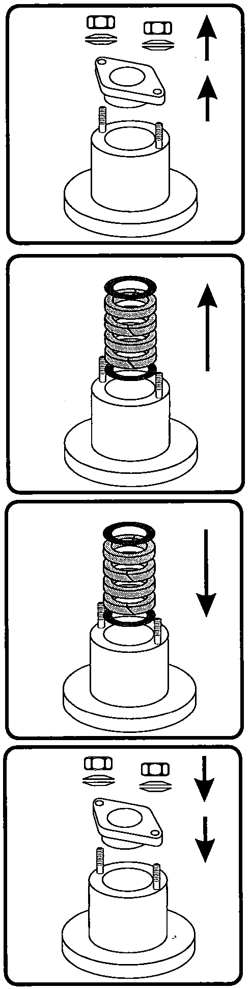
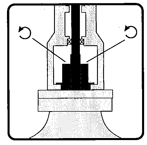
Cooling down the Vessel


CAUTION
High temperature processes also heat up the shaft in the agitator drive High-temperature processes result in heating of the shaft as far as the upper section of the agitator There is a risk of damage to the 0 rings if the buffer fluid is drained from the sliding ring seals too early or sliding ring seals are pulled onto hot shafts There is a risk of corrosion of bearings and bushing guides if attempts are made to pull sliding ring seals away from hot shafts or pull them onto hot shafts Before beginning work, let the container cool down so that the shaft temperature directly above the seal is at most 20o C above ambient temperature

Safety Rules

WARNING
Before beginning work on the agitator check that no explosive atmosphere exists.
WARNING
The shut-off device seals the vessel when the seal is removed However the overpressure inside the vessel must be reduced to an absolute minimum before proceeding further


WARNING
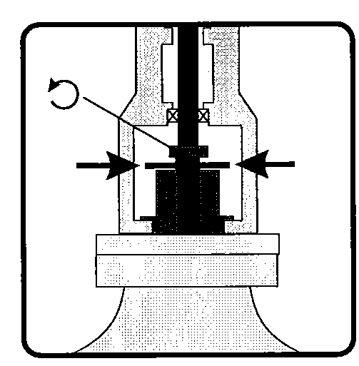
The bottom of the mechanical seal and the top of the shut-off device can be contaminated with product 一 if necessary provide protective equipment and cleaning measures The dead space between the mechanical seal and the shut-off device is under vessel pressure 一 instant discharge is possible upon loosening of the mechanical seal
CAUTION
Do not carry out work inside the vessel while the shaft is suspended
CAUTION
The relevant laws, accident prevention regulations and recognized technical regulations for safe and specialized work with this agitator should be observed This includes using protective equipment such as helmets, shoes, protective goggles and gloves Special safety measures should be taken when a container in which a poisonous or corrosive product has been processed needs to be entered(protective clothing, breathing apparatus).

● Switch-off the agitator ● Acc. to the local regulations either ♦lock the main switch or ♦pull the pertinent slide-in module at the control centre

CAUTION
Do not use the vessel, pipes or agitator drive as a climbing aid Provide a safe working platform
CAUTION
Work on the electrical installation may only be carried out by authorized personnel (e.g. company electricians)


● Disconnect the drive from the power supply

When other interfaces exist between the agitator and local facilities:

CAUTION
Obey safety rules when handling other subsystems, e.g. depressurize lines prior to their disconnection


● Disconnect other local installations (monitoring circuits, pressure supply, cooling water supply) from the agitator


Note on outdoor installation   When the agitator is assembled for installation at an outdoor location, all mating surfaces of components that are bolted together but are not contacted by the product (e.g. intermediate flange to agitator lantern, agitator lantern to mounting flange) must be sealed with a corrosion preventive (seam sealers) to preclude crevice corrosion.   Seam sealers are not included in the scope of supply.  

Dismantling/Reassembling
the Coupling Part A


S
C
 
Kupplungsteil Coupling part partie d’accouplement
Motor -oder Getriebeflansch Motor- or gearbox-flange Bride de moteur ou de reducteur


● See the parts list (→ chapter 8) for applicable parts For dismantling: ● Before removing the coupling part A measure and note the distance “C" from the bottom of the coupling part A to the bottom of the motor- or gearbox flange ● Loosen and remove the set screw (3020) ● Remove the coupling part A from the motor- or gearbox shaft ● Check the parts for damage For Reassembling: ● Slide the coupling part A onto the motor- or gearbox shaft and fix it in the position as measured before (distance "C") ● Apply thread locking agent on the thread, use LOCTITE® 243 ● nsert the set screw (3020) and tighten it (evenly, avoid bracing) Tightening torques for set screws: M10 30 Nm M16 80 Nm Check the gap "S” (S=0.3-0.8 mm), readjust if necessary

Usage of Nord-Lock Washers   ● Check the sectional drawing (when in scope of supply, → chapter 8) or the parts list (→ chapter 8) to find out where to apply Nord-Lock washers
During assembly ● At each location combine two Nord-Lock washers as shown(when delivered the washers are glued together in this orientation)


Where two elements are bolted together without gap:

♦ Tighten the bolts evenly with 15 percent higher torque than regularly recommended for the bottle, material and operating temperature (regular torque values → table chapter 4.4) — when the general assembly drawing, if provided (→ chapter 1), or the agitator cross sectional drawing, if provided (→ chapter 8), give torque values, these values already include the increase due to the Nord-Lock washers


Where two elements are bolted together with gap (e.g. bolting between mounting flange and vessel):

♦ Apply the regular torque values for this joint


Dismounting the Agitator Lantern   (EM with closed bearings, mechanical seal/stuffing box and shut-off device with clamping segments)   ● Attach the lifting gear such that the drive (1000/15000) can be removed (→ chapter 4.1 "Removing the Drive") ● Tension the lifting gear ● Remove the flange connection between the drive (1000/1500) and the lantern (3005) ● Remove the drive (1000/1500) ● Remove the protective grids (3080)   Version with mechanical seal: NOTE:Instructions with regard to actions on the mechanical seal (fixing segments, clamping ring, installation etc.) refer to mechanical seals made by ESD For mechanical seals from other suppliers refer to their instructions respectively (→ chapter 9)
● On the mechanical seal (5010) loosen the fixing segments (012), push them in and tighten them For mechanical seal with clamping ring (020): ♦ Loosen the clamping ring (020) For mechanical seal with set screws DIN 916 (with cup point) in the shaft sleeve (005): ♦ Loosen the set screws DIN 916    
● Drain the buffer fluid and disconnect the piping (5030) from the mechanical seal (5010)


Version with stuffing box:

● Loosen the stuffing box gland

For all versions:
● Remove the connection between the mounting flange and the seal housing and raise the seal up to the bottom bearing
In case the shaft does not slide down on the supension device: Push the shaft carefully ( 
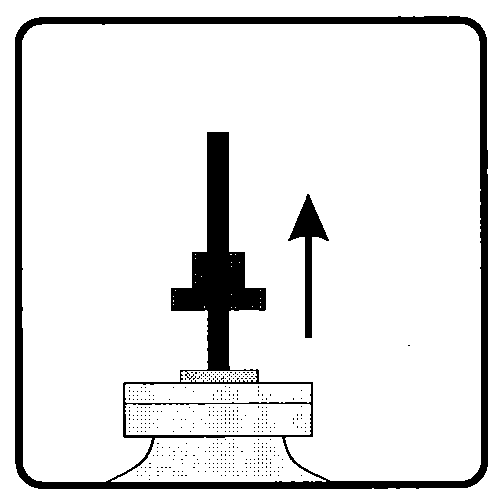
without force!) down until it rests on the: suspension device (5780)
● Fit a threaded rod to the coupling (3010), remove the coupling by means of a tie-bar
● Remove the bolt (3065) and the washer (3070) Now the shaft will slide down a few millimeters (5 to 10 mm) and rest on the suspension device

● Position the clamping segments (5772) on the mounting flange around the shaft and fasten them to the mounting flange using hexagon screws (5774)

Now the clamping segments press the suspension ring (5771) firmly into the mounting flange


● Remove the connection between the agitator lantern (3005) and the mounting flange (4500)

● Lift the agitator lantern (3005) from the mounting flange (4500) with a suitable lifting gear


CAUTION
When lifting the lantern of the agitator (3005) the shaft (3700/6000) shall not move upward

● Pull out the shaft seal (5010) with suitable devices


Replacing the Mechanical Seal
(if applicable)

● Carry out maintenance measures to the mechanical seal (→ chapter 9) or provide a replacement seal

● Make sure that on the new or overhauled mechanical seal (5010)

♦ the o-rings inside the rotating sleeve (005) are greased (PTFE-grease, "Chesterton")

♦ the shaft sleeve (005) is centered with the fixing segments (012) engaged

♦ the clamping ring (020) is loose or the set screws in the rotating sleeve are retracted resp.


Replacing the Stuffing Box Packing (if applicable)
● Insert the upper newgasket ● Mount the gland using the cup springs and nuts — do not tighten the nuts yet
● Insert the new lower gasket ● Insert new packing rings (size and quantity → parts list chapter 8), each new ring turned by 180° relative to the previous one
● Remove the gaskets and the packing rings
● Remove the nuts and the cup springs ● Remove the stuffing box gland

For all versions:

● In order to avoid damage to the o-rings inside the shaft sleeve (005) of the new mechanical seal/packing rings of the stuffing box:

♦ clean that part of the shaft over which the shaft seal will be pushed

♦ make sure that this part of the shaft is free from damage

♦ grease this part of the shaft with PTFE-grease ("Chesterton")


CAUTION
Push the shaft seal onto the shaft with utmost care and without tilting — danger of damage to the o-rings/packing rings

● Push the shaft seal onto the shaft (3700/6000)


Не нашли, что искали? Воспользуйтесь поиском:

vikidalka.ru - 2015-2024 год. Все права принадлежат их авторам! Нарушение авторских прав | Нарушение персональных данных